Written by Brendon O'Sullivan, in collaboration with Peter Gans. The program (StrongH.XLS, Excel 5.0/95 workbook) may be downloaded, free of charge.The workbook has 2 worksheets. On the first sheet calibration constants are determined from calibration data On the second sheet the calibration constants are used to adjust titration data in such a way that the adjusted electrode readings are linear in log [H+], as is required by Hyperquad and HypSpec. Both worksheets contain detailed instructions for use. Please note, this workbook contains a genuine, virus-free, macro)
The term pH is to be understood to signify -log10[H+] |
The classical Nernstian description of the response of a glass-bulb electrode is given by Equation 1,
|
(1) |
which gives the measured electrode potential, E, as a function of the proton (hydronium ion) concentration, [H+]. There are two constants in the equation, E0 and s. The first, E0, the standard potential or cell constant, gives the net electrical potential generated between the test solution and the reference cell. It is a function of the particular reference cell (usually Ag/Ag+ and located within the electrode), of the type of glass used for the electrode and of the junction potential formed at the interface between the test and reference solutions. The second constant, s, is the standard Nernstian slope parameter, ideally equal to RT/F (= T/5.04 mV or 59.128 mV at 298 K).
Normally the cell constant, E0, is just that, a constant. However it may vary if there is a significant change in the composition of the test solution since this variation changes the junction potential. This electrochemical potential is a well known phenomenon, theoretical treatments have been given long since (Henderson 1907, 1908). Indeed, these potentials are universally present in all potentiometric experiments which rely on an ionic bridge between solutions of differing electrolytic composition. Normally the junction potential remains constant but a correction must be applied for its variation when there is a significant change in the composition of the test solution's electrolyte, e.g. the substitution of potassium ions, K+, for protons, H+, as may occur when titrating to very low pH.
This error may be compensated for by including an extra term in the equation for the electrode response, the junction potential correction, jp, as in Equation 2.
|
E = Eo+ s log [H+] + jp [H+] |
(2) |
Note that the jp coefficient has the dimensions voltage/concentration. The use of junction potential corrections has been the subject of a relatively recent review (Baes, 1976). This source also gives a compilation of reported values for the correction term jp. Typical values/mV dm3 mole-1 reported when substituting H+ for any of the common alkali cations (Li+, Na+ or K+) vary between 20 and 60.
Equation 2 is a non-linear function of the unknown parameters E0, s and jp. Therefore calibration data must be analyzed by a non-linear least-squares procedure. Fortunately this is a relatively easy thing to do with modern computing packages. An example calculation is provided to accompany this document, which uses Microsoft Excel. Once the calibration parameters have been determined the electrode may be used to measure the pH in real samples. The spreadsheet file shows both how to analyze the calibration data and also how to apply the calibration parameters to correct electrode readings/mV to pH.
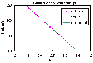
A typical calibration to low pH is illustrated in figure 1 (generated with StrongH.XLS).

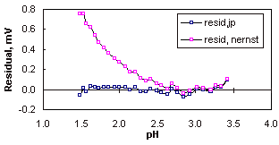
The linearity between pH and electrode potential, emf, is illustrated, on this scale the errors caused by the variation in junction potentials are not significant, but they become apparent when the scale is enlarged to show the difference between observed and calculated potentials (the residuals). When the correction for the junction potential is included the residuals fall to within a tolerance of ± 0.1 mV.

When allowance is not made for variation in the junction potential (i.e. the residuals obtained using only a Nernstian model (Equation 1) then the error becomes significant below pH 2.5, at this point the concentration of protons is 0.003 M which is 3% of the total electrolyte concentration (0.1 M KCl). Note that the effect of the variation in junction potential is relatively minor, even at the most extreme point in the experiment, pH 1.5, the junction potential correction is less than 1 mV and corresponds to error of only 0.014 pH.
'CO2 free' water may be used for the preparation of solutions (made by boiling distilled or de-ionised water and cooling under an inert gas), although this is hardly necessary for highly acidic solutions.
The simplest and most reliable method to calibrate the electrode is to dilute an acid stock (e.g. HCl, precisely standardized) into the test solution (e.g. KCl). This procedure has the advantage that it requires only one standardized solution, the acid. The best results will be obtained if the ionic strength is matched between the two solutions (e.g. use 0.1 M HCl and KCl). Incremental additions of acid should be selected so as to give at least 10 additions between pH 3.5 and 2.5 (where junction potential corrections are insignificant) and at least another 10 points by the end of the calibration. Choose the volumes of the additions so as to give an approximately linear variation in pH. Additions of acid may be made up to half the volume of electrolyte initially taken (e.g. a 50 mL solution of KCl may be titrated with up to 25 mL of HCl), greater additions tend to give poor results and are of little value since they give insignificant changes on the logarithmic pH-scale.
The concentration selected for the acid and electrolyte will affect the final pH, e.g. use of 0.1 M HCl/KCl limits the calibration to pH > 1.5, increasing the concentrations to 1 M limits the calibration to pH > 0.5
Use of a titration strategy , i.e. neutralization of an acid solution (e.g. HCl) with base (e.g. KOH) is not recommended since there are large variations in ionic strength when titrating such a highly acidic solution.
Select an electrode in which the liquid-liquid junction is in good condition, i.e. freely flowing and not fouled by precipitates, also ensure that the electrode filling solution is topped up. Place the electrode so that the level of the filling solution is well above the final level of the calibration solution; if the filling solution is below the level of the calibration solution then this will reverse the flow across the liquid-liquid junction and give rise to spurious potentials.
C.F. Baes and R.E. Mesmer, The Hydrolysis of Cations, 1976. Wiley, New York.
Henderson, Z. Phys. Chem., 59 (1907) 118.
Henderson, Z. Phys. Chem., 63 (1908) 325.